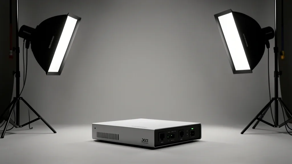
Defining the ultimate settings for the Ubiquiti UniFi Pro XG 8 PoE requires a deep understanding of high-density switching where massive throughput meets complex power delivery. As a Senior Field Specialist, I have audited countless enterprise deployments where architectural oversights in the 10GbE backplane lead to premature hardware failure or intermittent packet loss across high-demand VLANs.
Key Takeaways
- Understanding the non-blocking switching capacity is critical to preventing frame drops during peak traffic bursts.
- Strict adherence to Cat6a cabling standards is non-negotiable for stable 10GbE RJ45 performance.
- Proactive thermal monitoring and PoE budget management prevent unplanned downtime in enterprise stacks.
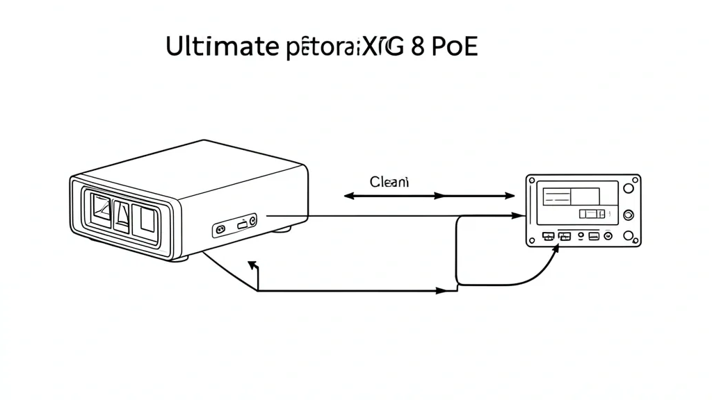
Technical Overview and Backplane Capabilities
The Ubiquiti UniFi Switch Pro XG 8 PoE is an industrial-grade aggregator. It features a non-blocking switching capacity essential for modern, data-dense enterprise demands. With four 10GbE SFP+ ports and four 10GbE RJ45 ports, it serves as a critical nexus for high-speed edge devices.
The backplane handles a total switching capacity of 160 Gbps. This ensures every port operates at line rate without cross-talk or congestion. Unlike entry-level gear, the XG 8 uses advanced internal buffers to manage bursty traffic from high-res surveillance systems and high-throughput servers.
You must balance your UniFi 10GbE SFP+ configuration against 802.3bt PoE++ budget requirements. If the internal power supply hits its limit, the switch dynamically throttles output. This can lower backplane efficiency if your port priority settings are not defined correctly.
Distinguish between L2 and L3 switching performance impacts on inter-VLAN routing latency. By offloading routing tasks to the switch’s ASIC (Application-Specific Integrated Circuit), you move traffic away from the CPU. This significantly lowers latency for sensitive, high-frequency network transactions.
Implement proper VLAN tagging and port profile isolation to ensure peak performance. This prevents broadcast storms from traversing the backplane and helps manage aggregate throughput. It ensures a single saturated port doesn’t impact the rest of the switch state.
Always consult the official UniFi hardware datasheet to verify internal throughput thresholds. Miscalculating these leads to bottlenecks that manifest as intermittent packet drops, which standard logs often fail to expose immediately.
Essential Technical Prerequisites
Start with a UniFi Controller version that supports the Pro XG 8 PoE feature set, ideally v7.x or later. Outdated controllers can break Switch Spanning Tree Protocol (STP) optimization, causing network-wide instability during topology changes.
Firmware matters. Run the latest stable release to support 802.3bt PoE++ standards reliably. Older versions often suffer from port-level power budget errors, where miscalculated draws lead to unexpected reboots during peak inductive loads.
Physical cabling is the most common failure point. For 10GbE RJ45 ports, IEEE 802.3an mandates Cat6a or Cat7 to mitigate alien crosstalk. Using Cat5e or Cat6 cables will force auto-negotiation down to 2.5 Gbps or 5 Gbps, effectively killing your throughput goals.
Configure Jumbo Frames across the entire end-to-end path. If one device in the chain—like a legacy camera or a misconfigured firewall—does not support an MTU of 9000 bytes, enabling this on the XG 8 will induce fragmentation. This spikes latency and CPU overhead.
Be strategic when mixing PoE, PoE+, and PoE++ devices. Perform a “power-budget-first” audit. Calculate the absolute peak draw of all connected devices and set a hard power limit in the UniFi controller to ensure the switch stays within its thermal overhead.
Check your SFP+ module compatibility. Refer to the Ubiquiti SFP compatibility guide to prevent link flaps caused by signal degradation. Use high-quality DACs or recognized transceivers to maintain signal integrity.
The Diagnostic Matrix: Reading System Telemetry
Interpretation of UniFi Controller L3 switching telemetry is the hallmark of a high-level admin. The dashboard provides granular port-level statistics. Cross-reference these with thermal management and fan curve profiles to detect component fatigue before failure occurs.
Analyze port-level telemetry for FCS (Frame Check Sequence) errors. A spike typically indicates a faulty cable or bad transceiver. Isolate these issues before the switch’s logic starts incrementing retransmission counts, which artificially caps port throughput.
Understand Flow Control and Storm Control for high-interference environments. Toggling these settings for the 10GbE SFP+ backplane prevents buffer overflow during micro-bursts that standard diagnostics might miss if the pooling interval is too slow.
Thermal logs are vital for long-term health. The Pro XG 8 PoE is an industrial device; high internal temperatures suggest poor rack airflow. Adjusting fan curves to ‘Cooling’ or ‘High’ is a temporary fix. The root cause usually lies in poor intake or exhaust clearance.
Monitor these metrics to move from a reactive to a proactive posture. Effective management of these telemetry streams keeps your switch environment optimized for modern enterprise traffic spikes.
Optimized Port and Power Workflow
Step-by-Step Port Configuration
Move away from ‘Default’ profiles. Navigate to UniFi Controller > Settings > Profiles > Port Management. Create custom profiles for specific hardware tiers.
- High-Bandwidth Workstations: Create a profile with ‘Flow Control’ enabled and ‘Jumbo Frames’ set to 9000. In Port Settings, use an Override to set the profile to ’10GbE-High-Perf’. Set ‘Speed/Duplex’ to ’10Gbps FDX’ rather than Auto to prevent negotiation drops.
- Power Profiles for PoE++ Devices: For high-draw devices like U6-Enterprise APs or PTZ cameras, define a custom Power Profile. Navigate to Settings > Power Profiles. Create a profile named ‘MaxPoE’ matching the device’s max wattage. Apply this in the Port Manager for each specific high-draw port.
- Enabling Jumbo Frames: Go to Settings > Networks > Global Network Settings. Enable ‘Jumbo Frames (MTU 9000)’. Warning: This must be consistent across the entire L2 path. Misalignment here causes catastrophic packet fragmentation.
Emergency Recovery and System Stabilization
Emergency Firmware Recovery via TFTP
If your Pro XG 8 becomes unresponsive after a bad update, do not RMA immediately. Perform an emergency recovery.
- Hard Reset: Hold the Reset button for 10+ seconds until the system LEDs flash. If that fails, move to TFTP.
- TFTP Mode Entry: Power off the switch. Press and hold the Reset button while plugging the power back in. Release only when the LED pattern indicates bootloader mode.
- TFTP Transfer: Set your PC’s static IP to 192.168.1.2. Use a TFTP client to push the firmware .bin file to 192.168.1.20 (the recovery IP). The switch will automatically flash and reboot.
Power Management Triggers
PoE over-subscription often triggers thermal throttling. If devices randomly reboot, check the ‘System Logs > Events’ for ‘Port Power Limit Exceeded’. Move secondary devices to external injectors to relieve the switch’s internal power supply.
Managing Common Bottlenecks and Pitfalls
The 10GbE “Auto-Negotiation” Fallacy
Copper SFP+ modules generate significant heat and struggle with cable-length resistance. The ‘Auto’ setting often oscillates because signal-to-noise ratios fluctuate under load.
Stable Duplex Configuration
Solve this by forcing duplex and speed. Navigate to Port Manager > Select Port > Speed/Duplex. Change from ‘Auto’ to ’10Gbps FDX’. If using 10GBASE-T transceivers, enable ‘Flow Control’ in the ‘Advanced’ settings to provide a buffer pressure valve.
Cable Grade Verification
Use Cat6A. Cat6 is unreliable for full 10GbE throughput over 30 meters. If you see high CRC errors in the ‘Statistics’ tab, replace the patch cable with shielded high-grade options to rule out EMI interference.
Long-Term Thermal and Maintenance Care
Thermal Management and Fan Curves
The Pro XG 8 is a high-heat device. It requires clear rack-mount airflow.
- Rack Placement: Use 1U of spacing above and below. Never stack high-heat devices on top.
- Environmental Monitoring: Check UniFi Controller > Dashboard > Switches > Pro XG 8 > Overview. If temperatures hit the ‘Yellow’ zone, ensure exhaust fans are venting hot air out, not recirculating it.
- Maintenance Audits: Every 90 days, audit logs for ‘Thermal Event’ warnings. Clear intake dust with compressed air monthly. Routine log analysis for ‘Port Link Down’ signals can identify failing optics before you face an outage.
📌 Save to Pinterest
Frequently Asked Questions
What is the maximum power budget available when using the Pro XG 8 with PoE++ injectors?
The Pro XG 8’s own power supply provides a fixed PoE budget. External injectors do not increase this budget; they simply offload the wattage from the switch. The switch remains responsible for managing its native power budget.
Should I enable Flow Control on all ports for a 10GbE environment?
Enable Flow Control on all active ports if you have bursty traffic like large file transfers. It prevents buffer overflows. Note that it may add slight latency to very small, sensitive packets; test this in your specific environment.
Why does my Pro XG 8 run hot when under full 10GbE load?
The Pro XG 8 manages heavy switching capacity. Copper-based 10GBASE-T transceivers generate significant heat compared to fiber. Ensure intake fans are clean and your rack has adequate CFM airflow.
Are there specific STP settings required to prevent loops with mixed L2/L3 infrastructure?
Yes. Set the Pro XG 8 as the ‘Root Bridge’ by setting the STP Priority to 4096. Set secondary distribution switches to 32768, and access switches to 61440. This hierarchy forces stable reconvergence.
How do I correctly configure port profiles to distinguish between IoT devices and high-bandwidth workstations?
Use VLAN tagging. Create separate ‘IoT’ and ‘Workstation’ VLANs and assign them to distinct Port Profiles. This fragments broadcast traffic, ensuring workstation performance isn’t impacted by IoT chatter.