Navigating Honeywell thermostat advanced settings demands a clear grasp of your HVAC system architecture. These configurations, found in the Installer Setup (ISU) menu, act as the command center for your climate control. They bridge the gap between your daily preferences and the mechanical triggers that keep your home comfortable.
Key Takeaways
- The ISU menu is your primary interface for fine-tuning HVAC performance.
- Correct cycle rate configuration is essential to prevent premature equipment failure.
- Always document baseline parameters before making changes; incorrect settings can void warranties or damage hardware.
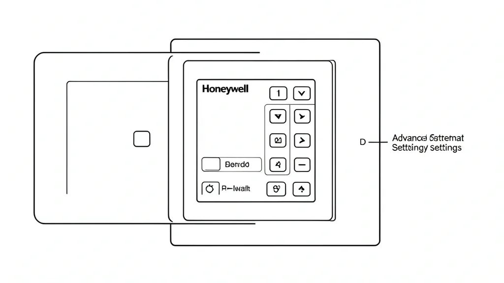
Technical Overview: Understanding the ISU Structure
The Resideo configuration menu varies significantly depending on your specific series, such as the T-series, Lyric, or older Vision Pro units. You typically access the ISU menu by holding a menu or secondary button for 3 to 5 seconds.
Think of every ISU setting as a numerical key-value pair. For instance, in a T6 Pro, ISU “100” might define your system type, while “200” covers heating stage control. These codes are not universal. A setting valid for one model might mean something different—or nothing at all—on another.
The menu relies on an installer hierarchy. You must first declare your hardware profile, such as gas furnace vs. heat pump. The thermostat dynamically gates future sub-menus based on this choice. If the system misidentifies your heat source, it may disable secondary stages or ignore auxiliary heat logic entirely.
Complexity scales with your smart home setup. High-end models allow for detailed control over dehumidifiers or ERV/HRV ventilators. Technicians must navigate this hierarchy with care. A “mis-configuration lock” can occur if settings are mismatched, causing the device to ignore safety sensors.
Check Resideo’s official product support portal for exact lookup tables. Never assume default factory settings are perfect for your specific home insulation and layout. The installer menu exists explicitly to allow for adaptive tuning to your home’s actual thermal load.
Diagnostic Matrix: When to Modify Advanced Parameters
Only enter the advanced menu in response to observable inefficiencies. Common issues stem from a poor calibration between the thermostat’s internal differential and your home’s thermal retention. If your furnace or AC starts and stops rapidly, you are likely facing “short-cycling.” This wears out compressor motor windings and kills efficiency.
Temperature drift is another red flag. This happens when the device sits on an interior wall without proper insulation behind the backplate, causing it to read “ghost” heat from the wall cavity rather than the actual room temperature. Advanced settings let you calibrate this offset for better accuracy.
Staged heating control is a frequent point of frustration. If a two-stage system dumps 100% capacity into a small room, it hits the setpoint too fast, leaving the rest of the house cold and hiking up energy bills. Adjusting these cycles provides a smoother, more efficient path to comfort.
| Symptom | Possible Cause | Quick Check | Resolution |
|---|---|---|---|
| Short-cycling | Incorrect Cycle Rate | Run-time under 5 mins | Adjust CP cycle rate via ISU |
| Temp Drift | Offset Error | Check with spot thermometer | Modify ISU internal offset |
| High Bills | Aggressive AUX Heat | Watch AUX status light | Delay AUX engagement time |
| Cold/Hot Spots | Stage Logic Mismatch | Verify threshold settings | Increase differential threshold |
If you experience spotty Wi-Fi, check the “C-wire power management” in the ISU. If you don’t have a dedicated common wire, the thermostat might be “power stealing,” which drops voltage to the Wi-Fi card during heating calls. Reviewing log data in these menus is often the first step in troubleshooting connectivity.
Prerequisites for Safe Menu Access
Before you touch the ISU, audit your hardware. Identifying your wiring is critical. A standard cooling unit can look like a dual-fuel heat pump; configuring this incorrectly could cause your heat pump and gas furnace to run at the same time, potentially over-pressurizing your ductwork.
Verify your power delivery. Smart sensors need constant voltage. C-wire management is the benchmark for stability. Never try to force advanced smart features onto a two-wire setup, as it limits processor speed and sensor polling. Check your transformer output at the furnace control board first.
Create a physical log or spreadsheet of every current ISU value before you start. This is your “emergency backup.” If the system stops firing or displays an error code, you need a record of your original settings to restore a functional baseline.
Always review Energy Star heating guidelines for your region. Extreme climates require different cycling behaviors than moderate ones. With a structured approach, you turn a risky experiment into a professional diagnostic adjustment.
Step-by-Step Workflow for Configuration
Navigating the ISU requires precision. Follow this standard professional workflow to avoid system conflicts:
1. Entry to the ISU Menu
Keep the thermostat on the home screen. Hold the ‘Menu’ (or gear icon) button and the ‘+’ or ‘Select’ button simultaneously for 3–5 seconds. If your model has an ‘Advanced’ menu, toggle to it. The display will show an ISU code, usually starting at 0110. Use the ‘+’ or ‘-‘ buttons to scroll through values.
2. Modifying Heat Pump and Fan Control
Find the ‘System Type’ (usually ISU 0170). Match this to your hardware: 0 for conventional, 3–7 for heat pumps. Once your type is set, go to ‘Fan Control’ (ISU 0300). Setting this to ‘Gas/Oil’ forces the furnace to manage the blower, preventing cold air from blowing through your vents. ‘Electric’ lets the thermostat control the fan directly.
3. Secure Saving and Exit
The thermostat does not save changes until you exit the menu loop. Once you finish your adjustments, press ‘Done’. The screen will blink or return to the main interface, which signals that your settings are committed to the hardware’s non-volatile memory (NVRAM).
Emergency Recovery and System Reset
Don’t panic if you trigger a logic lock or select the wrong fuel source. You can restore your controller without damaging the HVAC boards.
1. Soft Reset / Power Cycle
Remove the thermostat from its faceplate. Toggle the HVAC emergency disconnect switch at the furnace to ‘OFF’ for 60 seconds. This drains the capacitors. Re-seat the thermostat; it will often re-poll the system wiring and reset its internal state.
2. Full Factory Reset
If the system remains erratic, perform a hard reset. Go to ‘Menu’, select ‘Preferences’ (or ‘Installer Options’), and pick ‘Factory Reset’. This wipes all settings, schedules, and Wi-Fi data. You will need to re-commission the device as if it were new, so keep your wiring diagram nearby.
Common Pitfalls and Performance Hazards
Advanced settings are built for experienced technicians who know the recovery times of a building. Incorrect inputs can cause hardware failure.
1. Cycles Per Hour (CPH) Misconfiguration
The ‘System Cycle Rate’ dictates how many times per hour the system fires to reach your setpoint. Setting this too high—like 9-12 cycles for a standard furnace—induces short cycling. A compressor that cycles every four minutes will eventually overheat and fail, leading to an expensive repair.
2. Voltage and Stage Mismatches
Another hazard is setting a “two-stage” heating call when your system is only wired for one stage. This can trigger an ‘Auxiliary Heat’ relay that isn’t connected to anything, leaving you with a thermostat that claims it’s heating while the house stays cold.
Long-Term System Health and Maintenance
Your thermostat is the central nervous system of your home comfort. Treat advanced settings as a seasonal checklist item. Every autumn, verify your ‘Filter Reminder’ interval—usually found under ‘Maintenance Reminders’—is set to 90 days.
1. Calibration and Drift
Thermostat sensors can drift over time. Audit them by placing a calibrated digital thermometer within five inches of the device. If the variance is greater than 1.5°F, use the ‘Temperature Offset’ (Calibration) setting to sync the display with reality. This prevents the system from overworking to reach an inaccurate target temperature.
📌 Save to Pinterest
Frequently Asked Questions
How do I access the ISU installer setup menu?
Hold the ‘Menu’ or ‘Gear’ button and the ‘Select’ or ‘+’ button for 3 to 5 seconds. Once the screen shows a four-digit code like 0110, you are in the Installer Setup. From there, cycle through options to configure fuel, system type, and comfort stages.
Why does the set temperature not match the room temperature?
This is often caused by ‘Temperature Offset’ from wall-cavity drafts or sensor degradation. Verify the reading with an independent thermometer and use the ‘Sensor Calibration’ or ‘Temperature Offset’ setting to sync the display.
What are the risks of changing CPH settings?
Incorrect CPH settings cause ‘short cycling’. This triggers excessive wear on relays, contactors, and motors, which can lead to premature mechanical failure and wasted energy.
Do I need a pro to calibrate the sensor?
You can perform a basic check yourself. However, a professional can identify if the unit is suffering from internal wall drafts that a simple setting change cannot fix.
How do I reset to factory defaults?
Go to your ‘Menu’, select ‘Preferences’ or ‘Installer Options’, and find ‘Reset’. Select ‘Factory Reset’ to wipe all configurations. Have your wiring diagram ready, as you will need to re-program everything.