Mastering the whirlpool washer diagnostic mode is a mandatory skill for any technician or homeowner performing precision repairs on modern Vertical Modular Washers (VMW). As a veteran engineer, I’ve seen these control boards evolve from simple timers into sophisticated embedded systems. They now rely on iterative error LED patterns and EEPROM tracking to report machine health.
Key Takeaways
- Understand VMW controller architecture to differentiate between binary LED signals and alphanumeric display codes.
- Recognize that persistent fault codes often stem from EEPROM corruption, requiring a calibrated sensor reset.
- Always perform physical safety verification, including capacitor discharge, before touching the motor control unit.
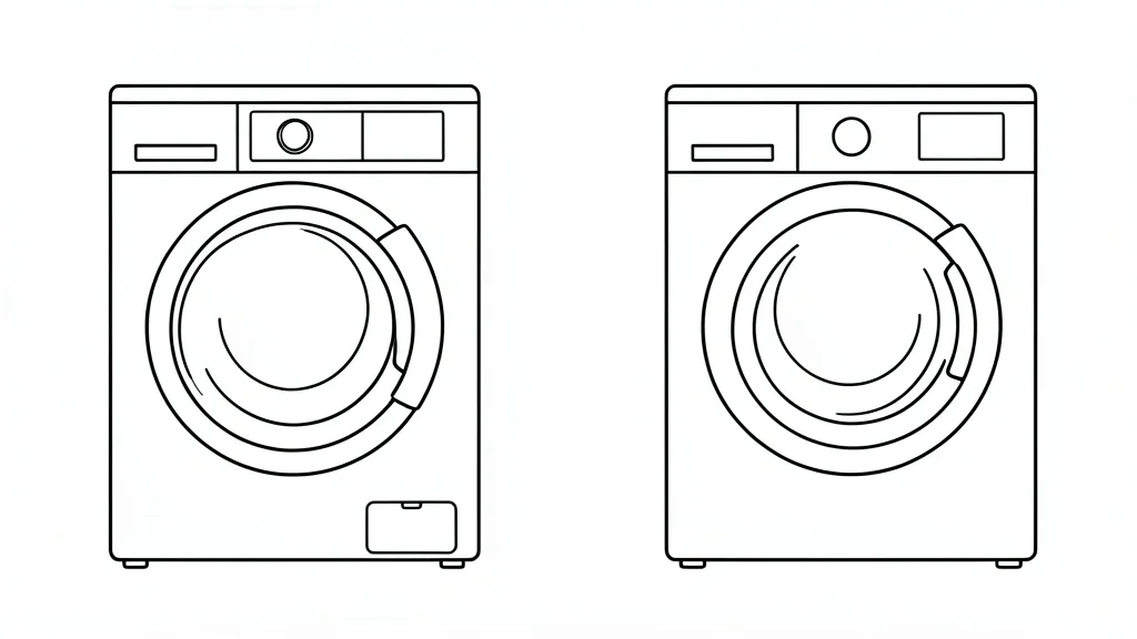
Understanding the Whirlpool Diagnostic Matrix
The VMW architecture uses a centralized User Interface (UI) board as the brain of the machine. On models with digital displays, the system shows plain alphanumeric fault codes. These boards store logic states in non-volatile memory for quick retrieval during service mode.
Models using LED indicators rely on a binary reporting structure. These washers use specific blink patterns to cycle through “F” (Fault) and “E” (Error) categories. Interpret these flashes carefully—the cadence and color are your only indicators of the machine’s state. Inconsistent patterns often point to a failed communication bus between the interface and the main controller.
The diagnostic matrix uses an Automatic Diagnostic Test Cycle to poll subsystems like the lid lock, water valves, and the drive motor. If the EEPROM detects a gap between expected sensor feedback and actual performance, the system logs the event. This prevents catastrophic mechanical failure by locking the machine down if a critical sensor variance occurs.
Keep your model-specific service guide handy. Check official Whirlpool documentation for parts lists. The shift from mechanical timers to digital modules has turned basic solenoid testing into a complex data acquisition procedure that demands patience and methodical verification.
Identifying Common Fault Code Categories
Fault codes provide a roadmap to the point of failure. The F0E1 code, for instance, signals a basket speed sensor malfunction, often tied to a loose motor control unit connection or a faulty hall-effect sensor at the motor base. This code halts the machine to prevent motor overspeeding.
The F5E2 code is a critical lid lock failure—the most frequent issue in the VMW line. The system cannot confirm the lid is locked, which blocks the actuator test. Check the latch for physical obstructions or broken housing tabs before assuming the solenoid has failed.
F7E1—often paired with F7E5—signals a shifter or sensor communication issue. This happens when the shift actuator fails to transition the gearbox between agitation and spin. Correct this with a calibrated sensor reset, which tells the board exactly where the mechanical gears sit, clearing out-of-sync memory bits.
Not all codes are permanent. Many are “soft faults” that clear after a successful cycle. If a code remains after power cycling, you have a “hard fault.” You must execute the manual clearing sequence to wipe the EEPROM and remove residual logic blocks.
| Symptom / Error | Possible Cause | Quick Check | Resolution |
|---|---|---|---|
| F0E1 / Speed Sensor | Motor Hall Sensor | Measure DC resistance | Replace motor/harness |
| F5E2 / Lid Lock | Lid Lock Assembly | Inspect latch damage | Replace lock; calibrate |
| F7E1 / Motor/Shifter | Shift Actuator | Check for burning odor | Replace actuator |
| Water Overflow | Pressure Sensor | Check tube for clogs | Clear trap; recalibrate |
Essential Safety and Prerequisite Checks
Safety begins with total isolation. Disconnect the power before touching the Motor Control Unit or UI board. These boards use high-capacity electrolytic capacitors; use a multimeter set to VDC to verify all residual current has cleared before touching any solder points to prevent high-voltage shock.
Verify your water supply pressure meets the 20 psi minimum. Many diagnostic failures occur during valve tests because the pressure dome doesn’t see a water level rise fast enough. The board marks this as a “Slow Fill” error, even though the cause is often just a kinked hose or a clogged intake screen.
Keep the drum empty. If the motor runs an automatic diagnostic with an off-balanced load, it will trigger false “Stalled Motor” or “Imbalance” codes. Perform a physical sanity check on the drum bearings and drive hub—if the hardware is shot, the diagnostic software will fail every time.
Consult appliance repair best practices for reference. Remember: diagnostic mode is a data discovery tool, not a repair tool. Combine electronic feedback with physical inspection. Use proper grounding to protect sensitive CMOS logic gates on the control board.
Step-by-Step Diagnostic Mode Execution
Activating Service Mode (The Industry Standard Sequence)
Improper timing causes most diagnostic attempts to fail. Ensure the washer is in standby mode (all lights off). If it was running, press ‘Power’ or ‘Cancel’ twice.
- Step 1: The Initial Reset. Verify the drum is empty and close the lid.
- Step 2: The Rotation Sequence. You must finish this in under 6 seconds. Start at 12 o’clock. Rotate the knob:
- 3 clicks clockwise.
- 1 click counter-clockwise.
- 1 click clockwise.
- Step 3: Verification. Console lights will flash or a chime will sound. If nothing happens, restart the sequence. Vary your speed; if you are too slow, the controller interprets this as standard input.
- Step 4: Navigating the Test Tree. Once in, clockwise rotation cycles through test IDs (t01, t02, etc.):
- t01: Saved Fault Codes.
- t02: UI/LED status check.
- t03: Water inlet valve tests.
- t04: Motor, lid lock, and pump tests.
Professional Tip: Record all four saved fault codes before clearing them. They are your breadcrumbs. Don’t skip this—the board often stores multiple issues in sequence.
Interpreting Results and Manual Calibration
Deciphering Logic Board Feedback
The display toggles between segments to show your code. The ‘F’ indicates the system area (e.g., F5 = Door Lock), while the ‘E’ identifies the specific circuit or sensor failure.
Executing the Calibration Cycle
Calibration is mandatory after replacing the motor, basket, or suspension. It teaches the board the ‘zero’ point for water levels and weight sensing.
- Step 1: Keep the washer empty and level.
- Step 2: Enter Diagnostic Mode, then rotate the knob until ‘Wash’, ‘Rinse’, and ‘Spin’ lights illuminate (or ‘C:00’ appears).
- Step 3: Press ‘Start’ with the lid closed.
- Step 4: The motor will oscillate to monitor the basket weight. This takes 2 to 4 minutes. Do not interrupt it.
The Hall sensor uses this to re-index the basket mass. Without calibration, the washer will ‘unbalance’ itself during spin cycles, even with a light load, because it is using outdated geometry data.
Troubleshooting Persistent Hidden Faults
The Purge Strategy
Sometimes, a washer still throws errors after a part replacement. This happens because the non-volatile memory (NVM) retains ‘Historic’ faults that keep triggering safety overrides.
- Access the Clear Function: Enter Diagnostic Mode and go to ‘t01’ (Saved Codes).
- The Long Press: Press and hold ‘Start’ for 5-10 seconds. When the LEDs flash, the buffer is purged.
- Power Cycle: Unplug the machine for 60 seconds. This discharges the capacitors and forces the BIOS to reload hardware status on boot.
Warning: If a code returns instantly, the issue is ‘Active.’ Stop testing and check for corroded wire harnesses. PCB-level connector corrosion is the #1 cause of ‘ghost’ codes that mimic sensor failure.
Preventative Care and Long-Term Reliability
Hardware Maintenance Lifecycle
Electronics are sensitive to moisture and vibration. Follow the ‘Three S’ rule: Sensors, Secure Connections, and Stability. Inspect wiring harnesses to the pressure switch and motor control unit (MCU) for chafing. Apply a thin layer of dielectric grease to every connector you touch to prevent the oxidation that causes intermittent communication errors.
📌 Save to Pinterest
Frequently Asked Questions
How do I know if I’ve successfully entered diagnostic mode?
Normal behavior stops. You should hear a chime, and the status lights (e.g., Wash and Rinse) will blink in a synchronized pattern or turn solid. If the display shows ’88’ or ’00’, you are in. If the machine stays in standby mode, your rotation sequence was likely too slow or irregular.
What if an F-code appears after the test?
Record the exact ‘F’ and ‘E’ characters. Search them against your model’s service manual to identify the affected system. Always check the physical wiring before replacing components, as vibration often causes connections to rattle loose.
Is it necessary to clear codes after a repair?
Yes. Clearing the NVM buffer ensures the control board isn’t basing future decisions on past failures. It’s best practice to use the long-press ‘Start’ method in ‘t01’ to start with a clean slate.
Why does the knob rotation sequence fail?
The controller uses pulse-counting. If your turns are too slow, the controller times out. Try a more fluid, rhythmic motion. Start from the dead-center ‘neutral’ position and ensure each click is definitive.
Can I calibrate with clothes inside?
Never. Calibration establishes the ’empty’ weight baseline. If you leave clothes in the drum, the machine will miscalculate capacity for every future load, leading to persistent balancing errors.